Recently Blog Entries
- Why Your Kanban Workflow Should Be More Than “In Progress”
- Two Questions to Help You Understand if You’re Doing Kanban
- Spike Abuse
- My Latest Article on Agile and Security
- Essentials of the Scaled Agile Framework
- A Possible Solution to the Issue of Test Data
- Project Sauron: A Long-lived, Stealthy and Likely State-sponsored Malware
- CCTV cameras used in massive botnet
- Sprint Planning: The Case for Finishing What You Start
- Scrum Retrospectives: Start, Stop… Continue? One of these things is not like the others…
Subscribe

Categories
Polls
 Loading ...
Archives
- May 2017
- April 2017
- September 2016
- August 2016
- June 2016
- May 2016
- April 2016
- March 2016
- February 2016
- January 2016
- December 2015
- October 2015
- September 2015
- July 2014
- January 2014
- March 2013
- February 2013
- January 2013
- December 2012
- July 2012
- May 2012
- April 2012
- January 2012
- November 2011
- October 2011
- September 2011
- August 2011
- April 2011
- October 2010
- August 2010
- July 2010
- June 2010
- May 2010
- March 2010
- February 2010
- January 2010
- December 2009
- November 2009
- October 2009
- September 2009
- August 2009
- July 2009
- June 2009
- May 2009
- April 2009
- March 2009
- February 2009
- December 2008
- November 2008
- September 2008
- July 2008
- June 2008
- May 2008
- April 2008
- March 2008
- February 2008
- January 2008
Admin
Search
Feb
4
Fundamentals of UML: The Requirements Diagrams
Posted by Keith McMillan
February 4, 2008 | 1 Comment
I’ve been intending to write an entry (perhaps more than one, don’t know yet) about the various Unified Modeling Language tools out there. At one point, I’d worked with more of these tools than anyone else I knew, and this gave me a bit of perspective on which tool was good for what particular use. Before I did that, I thought that it would be a good idea to do a few posts on the UML itself: what it is, why you care, and how you use it. This post covers the requirements model and diagrams, one of three broad categories of diagrams in the UML, the others being static and dynamic diagrams.
Model Visually
The old saw says “a picture is worth a thousand words.” While trite, it’s also true for documenting the designs of systems. Visual models are able to convey lots of information about the design of a system in a very succinct fashion, much more efficiently than a textual description. As with all languages, in order to communicate you need to have a common understanding, a vocabulary, in order to understand what’s being said.
The Unified Modeling Language [1][2] is just such a vocabulary. It was developed by Rational (since acquired by IBM) in the 1990s. At that time, Rational brought together three of the leading experts in object-oriented systems, Grady Booch, Ivar Jacobsen and James Rumbaugh, and combined the best of their respective techniques to create both the UML and the Rational Unified Process. The UML was refined from their earlier modeling languages (Booch Notation, OMT). Since then, Rational has given control of the UML to the Object Management Group, who now shepherds what has become an industry-standard visual modeling language.
The Unified Modeling Language defines a number of types of diagrams to represent various aspects, or ways of looking at a software system. These break down broadly into three categories of diagrams: requirements diagrams, static and dynamic diagrams.
The Requirements Diagrams
UML defines use case diagrams to allow allow you to capture the requirements of your system. Use case diagrams show actors (people or systems external to the one being described), use cases, and the relationships between them. Use cases are discrete, self-contained pieces of functionality performed by the system in collaboration with the actor. As an example, a use case for an online shopping system might be “Add Item to Shopping Cart”, or “Update User Profile”.
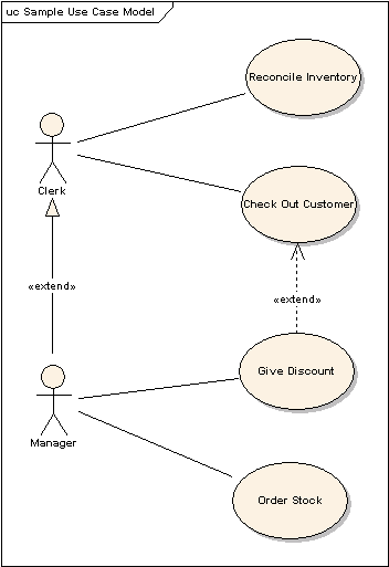
The requirements model is more than just the use case diagrams, however. The requirements model is defined as the set of all use cases, actors and their relationships, and it can exist even if no use case diagrams are created. More on why that’s important in a bit.
Use cases themselves are not specified (read: fully written up) in the UML. That’s usually done in word processing programs such as Microsoft Word, or in special purpose programs such as Accept 360 or Rational Requisite Pro. In fact, many successful development projects completely forgo creating use case diagrams altogether. Given that your requirements aren’t captured in UML, what are some reasons you would want to create one or more use case diagrams?
Reasons to Create Use Case Diagrams
One reason to create a use case diagram is to allow you to easily picture all of the functions of a system, and who is using those functions, graphically. It’s typical to have just such a diagram, one that has every actor, every use case, and the relationships between them. This sort of diagram facilitates conversations with customers, developers, testers, and other stakeholders in the development. It allows you to get the “big picture” of the functions of the system.
You can also create a diagram per actor, showing only the functions that the actor in question is expected to use. These sorts of use case diagrams allow conversations to sanity-check these associations, and can help you identify additional functions that a user of the system requires, but that is not currently captured.
Another variant of use case diagram is just the opposite, it shows an individual use case, and all the actors that are associated with it. This sort of diagram is useful for visually capturing security information: who’s allowed to use a particular function.
Use case diagrams also serve as an easy way to get the use cases as entities into the UML modeling tool, although they’re not necessary for this. Once a use case exists in your modeling tool, it becomes part of your requirements model, and you can associate static and dynamic diagrams (we’ll talk about these in a subsequent post) with use cases, showing how the system accomplishes the functionality in the use case. This establishes traceability.
Traceability
Traceability is a very powerful tool. Once you understand the relationship between a use case and the static and dynamic structures in your system support it, you are in a much better position to understand what the impact of any change to the use case means to the design. Even more powerfully, you can now understand the opposite as well: what use cases may be impacted by a change to the design of the system. Without traceability from requirements to design, this type of understanding is very likely an educated guess.
Some businesses may even choose to model entire business processes using use cases, not just those for a particular system that’s being developed. These are called business use cases and the business use case model. These sorts of models help business analysts understand how the business works, and what part software systems, departments and people play in the larger context of performing a business task. This is well beyond what many businesses are prepared to do, so don’t fret if it seems a bit academic.
The Skinny
Use case model diagrams are marginally helpful. They provide a nice, if not essential overview of all of the functions of a system, along with their associations to the actors involved, which can enable conversations.
The use case model, on the other hand, is extremely useful, as it allows us to establish traceability. Traceability is a very powerful tool to understand the impact of changes, either to the design as a result in change in requirements, or in the requirements as a result in change to design. It’s entirely possible to forgo use case model diagrams, but the use case model is a valuable tool that should be used for projects of any significant size.
Next, we’re going to look at dynamic diagrams in the UML.
Comments
1 Comment »
Blogroll
- Ars Technica
- Dark Reading - IT Security
- Help Net Security
- InformIT
- SANS Internet Storm Center
- Schneier on Security - Dr. Bruce Schieier’s blog
- Security Info Watch
- What to Fix - Daniel Markham, fellow consultant
- Wired Gadget Lab
- Wordpress Documentation
- WordPress Planet
- Wordpress Support Forum
[…] previous posts in this series, we’ve discussed requirements diagrams (use case diagrams) and commonly used behavioral diagrams in the Unified Modeling Language (UML). […]